Thursday, December 7, 2023

Parallel or Series


https://sailtortuguita.blogspot.com/2023/12/parallel-or-series.html

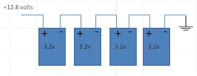
For a small battery bank, like 100 Amp hours (Ah), you can put four 3.2 volt, 100 Ah cells together in series to get a 12 volt 100Ah bank like shown below.  If you need more capacity, you can put another bank in parallel with the first to give 12 volt 200Ah.

4S2P with multiple Daly BMS
There are a couple of problems with this type of arrangement.  Each 100Ah bank needs its own BMS so 5 banks need 5 BMS's.  That gets expensive but does provide some level of redundancy.  If one bank goes bad or a BMS fails, you can always pull the bad section out and you still have a workable system.

These type of BMS's use FET transistors to shut off charging or discharging protecting the cells.  In theory, if all 5 banks are perfectly equal, each bank will share the load with every other.  If for example, your fridge draws 20 amps, each bank would provide 4 amps.  Like any DC system in parallel, like alternators, batteries, or solar panels, there are small differences and imbalances occur.

So you may even have all 20 amps being provided from one bank with the others providing nothing.  That's worst case but they never balance out.

There is not a BMS that exists that would solve this problem but one could be made if it had network communication between and PWM output from each and every BMS so that they can all coordinate and output the same power.  Unfortunately nobody make such a thing.

The FET transistor switches of these small BMS's, like any transistor, have maximum power ratings and are destroyed by heat.  I do not think it is prudent to trust the health of your boat's electrics to a possibly under-rated cheap Chinese transistor.  Unbalance between the BMS outputs may very well cause a single FET maximum current rating to be exceeded sooner than expected.

An example I saw was that a friend had his banks 'either/or'.  One bank would put out all the power until it's voltage was low enough that it would then be taken over by the other bank which would then put out all the power.  This would go back and forth until they needed to be recharged.  Rinse, repeat.

I would think what happens on the charging mode is similar except, if a cheap Chinese FET fails to cut off the charging source, that's when you could get a fire.

One last thing that I have seen with series is that one battery acts as a charging source for the other. The power goes back and forth between the parallel banks and some capacity gets lost as heat to the balance shunts.  So if you let these sit for extended periods, you could come back to your boat with discharged batteries.

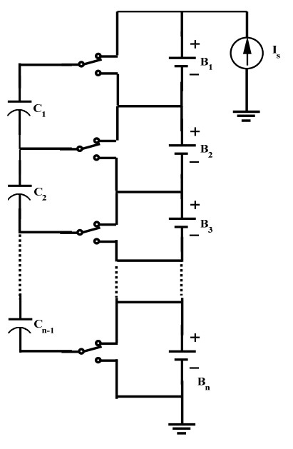
We installed a 12 volt, 1000 Ah system made up of 40 3.2v 100Ah cells.  To do this as a series first parallel second system would need 10 BMS's at $150 each and have all the problems described above.  The nomenclature for this would be 4S10P.  That means 4 in series first and 10 of those in parallel second.

 So, what to do?  Go with Parallel first and Series second.  That would be 10P4S.

These are our 40 cells as 10P4S
With this configuration, you hook 10 cells together in parallel giving 3.2v 1000 Ah and then connect 4 of those groups in series which brings the voltage up to 12 volts.  A big advantage of this design is that it only requires one BMS.

The good thing with Parallel first is that all the parallel cells stay balanced, they have to stay balanced because they are all connected together.  Then you only have 4 series banks that need to be balanced by the BMS.  

So, the BMS is connected to each 3.2v 1000 Ah bank.  Each of these banks are kept in balance by the BMS which reads the individual bank voltages and trips the appropriate relay for charge or discharge protection. 

Since the BMS needs a very good way to shut off charging and discharging, FET transistors are a very bad choice.  Relays are a much better and reliable choice.  They can handle much more power and can be manually switched in an emergency.  I chose the Blue Sea ML-RBS 7700.  They can handle 500 Amps continuously and will handle 300 Amps while switching.  I will never be able to supply or discharge that much current on our boat.


Tuesday, November 21, 2023

The Balancing Act

 https://sailtortuguita.blogspot.com/2023/11/the-balancing-act.html

It's fairly easy to read the battery voltage.  It is your system voltage.  It can be measured just about anywhere wires run for your 12 (or 24) volt system.

The battery bank on the right is a typical 12 volt Lithium parallel cell arrangement.  Each cell contributes 3.2 volts for a total system voltage of 12.8 volts.

This is assuming that all the cells stay at the exact same charge state ie: voltage. 

If the charger is set to shut off at 12.8 volts (full charge) and one cell is unbalanced at .2 volts below the others, then the 3 good cells would reach 3.25 volts each and the low cell would be 3.05.  That's will put the good cells further into the Knee.

However, if an unbalanced cell is .2 volts above the others, then that cell would be at 3.35 volts when the bank is fully charged to 12.8 volts while the others have only reached 3.15 volts.

Shunting Transistors for Balancing
In this case, the 3.35 volt cell will probably enter thermal runaway.

So not only must a BMS be able to monitor the voltage of each cell and shut off charging when any cell exceeds a certain voltage but it must be able to take some voltage from a high cell and put it into the others.  This balancing can be either Passive or Active.   

Passive balancing is accomplished with transistor controlled shunts which dissipate higher voltage cells into resistors.  

In an Active system the BMS switches transistors which redistribute energy in the out of range cell into a capacitor which then is switched into one of the lower voltage cells.


There are 2 types of BMS's.  Distributed and Centralized. 


Emus Distributed BMS
Centralized BMS's have wires that run to the cells and the sensors are internal to the BMS itself.  Generally, this type of BMS will not have temperature sensors for each cell but one or two bank temp sensors.


Distributed BMS's have their sensors mounted out on the cells in the bank and a network connects the sensors to the BMS 'the brain'.  The Distributed cell sensors will sense both voltage and temperature

I thought a Distributed system was silly since the distance between the cells and BMS were so short it didn't seem justified for all the complexity involved.

I started out thinking the Chargery BMS was a good way to go.  It was a low priced centralized system that included a display and charger.

I bought one and still have it sitting on the boat because I decided not to use it due to it's overly complex setup options.  It also appears to have passive balancing.  It would be easy to drain your system with a minor settings mistake and having the passive balancer shunt your cells down to zero.

I ended up choosing the REC Active BMS for our installation.  It is a very robust, weatherproof, BMS geared toward marine installations vs. Electric Cars.  It is fully CANBus compatible and plays friendly with Victron hardware and displays.  The biggest downside is terrible customer support.  I will have more on the REC in future posts.


Wednesday, October 4, 2023

BMS and the Knees

BMS stands for Battery Management System.  It provides two things, Protection and Balancing.  If it doesn't do those two things, you don't want it.

Lead batteries have a linear charge/discharge profile. The percentage of charge is directly related to the voltage.  12.8 volts is fully charged, 12 volts is 50% and 10 volts is pretty much dead.

The Lithium profile is quite different.  You could be 90% charged at 13.3 volts and have 20% remaining at 13.1 volts. 

Because of such a narrow voltage range, we can't use voltage tell the charge of a Lithium battery.  A device needs to keep track of how much power goes in and out and use that as the State of Charge (SOC).

The big problems happen where the curve goes from basically flat and around the corners (The Knees) during the final stages of charge or discharge.  At the Knees, a little bit of charge goes a long way with regards to the voltage.  

The battery could be charging nicely at 13.3 volts and be 90% charged, It could have even taken all day to get from 13.1 volts (20% SOC) to this point.  Then in a matter of minutes the voltage could go to 14 volts and Thermal Runaway a few minutes later. 

The BMS is what provides protection at the Knees.  A good BMS is imperative in any installation.


Thursday, September 28, 2023

Lithium Battery Conversion

Our Lead-acid batteries were pretty anemic from the day we got them.  After 2 years of sitting uncharged during Covid, they were essentially scrap.  The plan had always been to install Lithium batteries on the next replacement cycle, which is now. 

In the beginning, Lithium seemed buggy and I didn't want to be an early adopter of a completely new technology and be stuck without electricity in far remote locations.  

There always seems to be a new and better technology just around the corner but how long do you wait?  LiFePO4 batteries have been in use for 20 years.  With all the advances and a huge amount of data from installed units, I felt the time had come to take the plunge.     

Prices have come down so much that the batteries themselves are now less expensive than Lead.  An expensive part of the conversion is the new infrastructure needed to manage the batteries.  This includes new wiring, Battery Management, Displays, and Charging.  The initial investment in infrastructure will always be of use in any future battery installation on the boat.

When starting this project, I was warned about how much misinformation was floating around the internet.  There sure was, and still is.  My best go-to resource was the Nordkyn Engineering series of articles.  Soggy Paws has also done a nice how-to with top notch information.

There are numerous advantages to Lithium over Lead-acid batteries and that is uncontroversial so I will let you search for things like weight, capacity, ampacity, and longevity on your own.

A big question that always comes up is "what about fires". 

Lithium batteries have a history of fires but those batteries, like the ones in cellphones and e-bikes, are Lithium Ion, not Lithium Iron.  LiFePO4 batteries and related chemistries have an extremely good safety record if installed and maintained correctly.  

It is important to understand that a good Lithium system is just just Plug-n-Play.  However, there are many bad Plug-n-Play installations out there that are giving Lithium a bad reputation.

Below is a dramatic video showing Thermal Runaway of a GBS 12V 240Ah bank that was initially managed with an Orion BMS.  This event happened one night back in March just in our boatyard in Malaysia.  Fortunately they got the battery off the boat before any damage was done.

In the video, there is only one cell that went into Thermal Runaway.  This was from a charging overvoltage, an electrical issue.   However, it would have spread thermally to the other three cells if the bank had not been separated.  

A Lithium Battery fire is essentially a chemical fire that requires no oxygen to burn and therefore can not be smothered.  Normal fire extinguishers won't work since they attempt to remove oxygen from the combustion and that's not what's going on here.  I think the best way to deal with a fire like this is to throw it overboard to get it cooled down.

The design of this system was solid but the owner really didn't understand the limitations of Battery Management and Cell Balancing.  He treated it like a regular battery and tried to charge it with a car charger.  That did not turn out well.

I have helped quite a few cruisers with their Lithium installations along with getting tours of existing systems.  I tried to take the best of everything when doing my design.  The next group of posts will hopefully put the practical and theory together for those following the more challenging path of a Lithium Battery conversion.